IEC 60770-2:2010 pdf download – Transmitters for use in industrial-process control systems – Part 2: Methods for inspection and routine testing
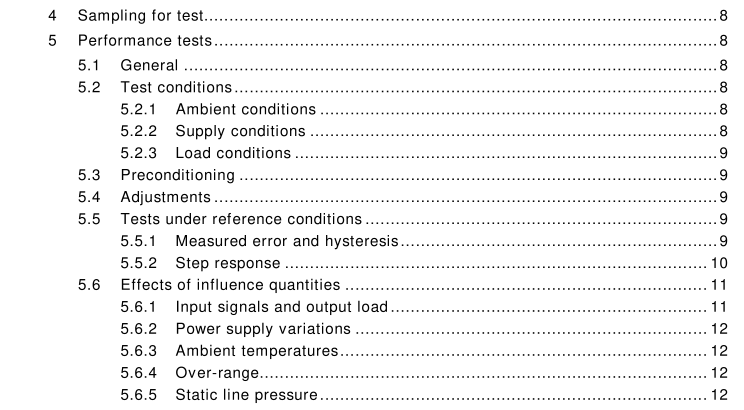
5.6 Effects of influence quantities
5.6.1 Input signals and output load Input signals: the tests described in 5.6.2, 5.6.3, 5.6.4 and 5.6.5 shall each be conducted with input signals of 0 % and 1 00 % of span if the transmitter output is able to go at least 2 % below its lower range value and at least 2 % above its upper range value. Otherwise, suitable input signals such as 5 % and 95 % of span shall be substituted. Output load: electrical transmitters should be connected to maximum rated output load (for current output).
5.6.2Power supply variations
Using each chosen input signal,the user shall measure and report the change of output inpercentages of span at the following variations in power supply or at the manufacturer’sstated limits, whichever is smaller:
Voltage variation: +10 % to -15 % of nominal a.c. voltage and +20 % to -15 % for nominald.c. voltage (IEC 61298-3)(for 2-wire transmitters the load has also to be taken in account).
Pneumatic supply pressure variation:+10 % to -15 % of nominal pressure (IEC 61298-3).
5.6.3 Ambient temperatures
The user shall measure and report at 0 % and 100 % input signal the change in observedoutput signal.This shall be carried out at each of the following ambient temperatures:
a) 20 c (reference);
b) maximum operating temperature specified by the manufacturer;
c) 20 °C;
d) minimum operating temperature specified by the manufacturer;
e) 20 °c;
The tolerance for each test temperature should be t2C and the rate of change of ambienttemperature should be less than 1 °C per minute.
Before measuring the influence effect,sufficient time (usually 3 h) shall be allowed forstabilization of the temperature of all parts of the transmitter.
Output changes shall be reported as percentages of output span.
NOTE This test may be omitted only where there is no concern about ambient temperature effects.5.6.4over-range
Before this test,measurements of the output shall be performed at 0 % and 100 % inputvalues.The input shall then be increased to the maximum over-range value specified by themanufacturer. After the over-range value has been applied for 1 min,the input shail bereduced to the nominal lower range value.After a further 5 min have elapsed,using thesame input levels as before, determine the changes in observed output values.
Differential pressure transmitters are to be tested for over-range effects in both directions.They shall be tested as described above, first over-ranging the positive chamber and thenover-ranging the negative chamber. The changes in output, determined after over-rangingin each direction, shall be reported.
Output changes shall be reported as percentages of output span.
5.6.5 Static line pressure This test shall be carried out on transmitters which in normal operation are subjected to line pressure. Before this test, measurements of the output shall be performed at 0 % and 1 00 % input values. The pressure shall be changed from atmospheric to the full working pressure of the instrument. For some applications, this test may also be required to be performed at pressures below atmospheric pressure. Using the same input levels as before, the changes in observed output values shall be measured.
NOTE Measuring the static pressure influence with inputs other than zero differential pressure is very difficult torealise for differential pressure transmitters. If this should be required, a separate agreement between manufacturerand user is recommended.
Output changes shall be reported as percentages of output span.
6 Test report and documentation
A complete test report of the evaluation shall be prepared after the completion of the tests.The test report shall have the following generic lay-out:
.Title page with
– abridged name and type/model number of the instrument;
name of the manufacturer;
name and address of the laboratory;
– names and signatures of evaluator and his next principal (report authorizer);- identification code of the report and date of issue.
.Introduction with
– aim of the tests;
– name and address of the manufacturer;
model,type,serial number and date of manufacture (or final assembly) of theinstrument;
short description of the instrument, type and number of sensors,measuring range,recording method,measurement intervals,memory size in terms of number ofmessages, supply and energy consumption;
– period and year in which tests are performed;
– test methods used and test methods omitted or varied.. Conclusions and test results with
– summary with conclusions with respect to the applicability based on the test results and other qualitative findings;
– table in which all test results are conveniently arranged.
All the original documentation related to the measurements made during the tests shall bestored by the user for at least two years after the report is issued.
