BS IEC 60462:2010 pdf download – Nuclear instrumentation – Photomultiplier tubes for scintillation counting – Test procedures
60462 lEC:2010(E)
least 20 times the DC anode current.Alternatively, the potentials between dynodes for thedynodes drawing the greatest current may be individually stabilized (as with separate powersupplies).
Charge-storage capacitors may be effectively used across the dynodes or from the dynodesto ground when the ratio of the peak anode current to the average anode current is large andthe capacitor can maintain the required dynode potentials for the duration of the pulse.
Pulse shaping methods and time constants suitable for optimum performance should be usedand should be stated.
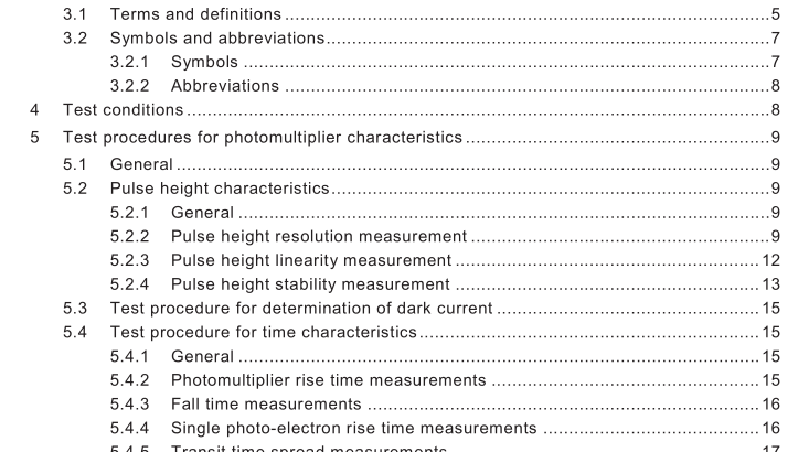
5 Test procedures for photomultiplier characteristics
5.1 General
ln addition to the specifications and test methods of lEC 60306-4, complementary or extendedspecifications and tests required for photomultipliers used with scintillation and Cherenkovdetectors are:
a)Pulse height characteristics 1.
b)Dark current.
c)Pulse timing characteristics.
5.2 Pulse height characteristics
5.2.1General
Pulse height is used in counting and spectrometric applications.
5.2.2Pulse height resolution measurement
5.2.2.1General
ln general there are four distinct PHR measurements to define the photon-and-electronresolution of PMT and scintillator/PMT combinations. These resolutions may be usedseparately or together.
5.2.2.213Cs PHR for a scintillator/PMT combination
This PHR is a function of the photocathode quantum efficiency, collection efficiencies of thedynodes and spatial uniformity,as well as the resolution of the scintillator.
For standard cases, measurement of 13’cs pulse height resolution requires a 13’Cs source, aNal(TI) scintillator of 50 mm height and approximately the same diameter as thephotocathode,a pulse height analyzer and the photomultiplier to be tested. Thephotomultiplier tube is optically coupled to the scintillator – for example,with the aid ofsilicone grease or viscous oil.The crystal housing should be at photocathode potential.Thesource is placed at a distance from the scintillator such that less than 1 000 pulses/s areencountered.
Phosphorescence of the scintillator and the PMT window may require 1 2 h to decay to a sufficiently low level to permit accurate measurements to be made. Therefore, photomultipliers and scintillators should not be exposed to ambient light for 1 2 h before measurements are made. The test enclosure shall be designed to avoid high electric fields in the region of the photocathode.
If the PMT is operated with ground potential at the photocathode (positive high voltage) there is little problem with external electric fields at the photocathode. If negative high voltage is used, electric fields near the photocathode should be low. This may be accomplished by an electrostatic shield at photocathode potential. Otherwise, excessive noise on the output signal, followed by eventual loss of photosensitivity, may develop. As with all PMT measurements, a magnetic shield is required.
The 1 37 Cs distribution should be displayed on a pulse height analyzer and so positioned that the upper half of the full-energy peak distribution spans at least eight channels. The total counting rate should not exceed 1 000 s –1 and the integration and differentiation time constants should not exceed 5 μs. At least 50 000 counts shall be contained within the channels comprising the FWHM. Pulse height resolution (PHR), in percent, is obtained from:
where
R pulse height resolution in percent;
∆P FWHM as shown in Figure 1 ;
P pulse height corresponding to the peak value of the distribution.
A linear interpolation should be made to determine the value ∆P. Alternatively, other curve- fitting techniques may be used. The method employed should be described. In the case of a computer-controlled pulse height analyzer, a different method can be employed to determine the FWHM by assuming that the upper-part of the full energy peak approximates a Gaussian distribution. While the observed distribution is usually slightly skewed and not truly Gaussian, PHR values determined on the basis of a Gaussian distribution will, in general, agree closely with values obtained from the former method.
5.2.2.3 Light emitting source PHR This PHR (intrinsic photomultiplier resolution) is obtained with a light emitting source such as a light emitting diode (LED) (see Annex A), calibrated to provide a 1 37 Cs- Nal(Tl) scintillator – equivalent signal (or stated number of photoelectrons per pulse). The light emitting source PHR is considerably smaller than the scintillator/PMT PHR because the contribution of the scintillator is not present. The light emitting source PHR should be stated in terms of a 1 37 Cs-equivalent flash; the light emitting source should be adjusted in flash intensity until the resulting pulse height distribution exhibits a peak in the same channel as a Nal(Tl) scintillator and 1 37 Cs source combination. The light emitting source shall be positioned such that it uniformly illuminates the photocathode. PHR may be calculated from the previously discussed method (see equation 1 ). The integration time of the electronic circuits shall be much longer than the duration of the light flash and the time constant of the scintillator.BS IEC 60462 pdf download.
